G = Gearbox
A = Automatic
6 = Number of gears (speeds)
HP = Hydraulic planetary gear
26 = size
Z = Gearbox manufacturer ZF (Zahnradfabrik Friedrichshafen)

BMW has developed a new automatic six speed gearbox together with ZF (Zahnradfabrik Friedrichshafen), designated the GA6HP26Z for the E65. It represents a further development of transmission technology and features innovations used for the first time in BMW automatic gearboxes. This gearbox makes an important contribution to the “revolutionary” features of the E65 in the luxury class segment.

The GA6HP26Z is designed in two versions for the different E65 engines. There is a more powerful version available for the V-12 that differs with the following components:

  • Power output and torque characteristics
  • Torque converter
  • Clutches with different numbers of steel discs and lined plates
  • Lepelletier planetary gear train with a different number of planet gears

The gearbox used in the 745i is designed for a torque of 440 Nm. The more powerful version (760i) is designed for a power output of 320 kW/435 bhp and a torque of 600 Nm. The
fundamental design and function of both gearbox versions are the same.

To match the installed position of the engine, the automatic transmission is also arranged longitudinally. It uses the planetary gear train principle, with hydraulic-electronic control; the hydraulic and electronic control units form a composite element that is installed as a single unit inside the automatic transmission and referred to as “Mechatronik”.

A new feature is decoupling of the transmission when the vehicle is at a standstill, that is to say instead of the engine remaining connected to the converter and the vehicle being prevented from moving by  applying the brake, the converter is disconnected and only a minimum rotating load remains. This has the effect of further reducing fuel consumption. The electronic transmission control uses a newly developed shift strategy

For this, please refer to the separate functional description.

The 6HP26 automatic transmission is about 13 % lighter than the previous 5-speed unit, accelerates 5 % faster and uses about 7 % less fuel.
It also contains fewer components:

    • 5-speed transmission app. 660 parts
    • 6-speed transmission app. 470 parts

The 6-speed automatic transmission is 5 centimetres shorter than the 5-speed transmission.
Engine power reaches the transmission via a hydrodynamic torque converter with integral converter lock-up clutch.

The input torque limits are:

    • 6HP19 max. torque: 420 Nm
    • 6HP26 max. torque: 600 Nm
    • 6HP32 max. torque: 750 Nm

The 6 forward gears and 1 reverse gear are obtained from a single-web planetary gear set followed by a double planetary gear set.
Using these Lepelletier-type gear sets, it was possible to obtain 6 forward speeds.

Mechanical Design of the Gearbox

The mechanical power transmission of the gearbox has been optimized with regard to gearshift comfort, quality and reduced fuel consumption. The engine torque is transferred
to the gearbox by a torque converter with a controlled lockup clutch. The six forward gears and the reverse gear are produced by a Lepelletier planetary gear train. The gears are shifted by multi-disc clutches.

1. Output shaft
2. Double gear train
3. Clutch D
4. Clutch C
5. Clutch E
6. Clutch B
7. Clutch A
8. Single gear train
9. Oil pump
10 Torque converter with lockup clutch

The new automatic gearbox has the following advantages:

    • Designed as a 6-speed gearbox with an overdrive ratio in 5th and 6th gear, fuel consumption
      is reduced by up to 5 percent.
    • The 6-speed gearbox allows for more gear spread, improving vehicle acceleration.
    • The new 6-speed gearbox is approximately 30 kg lighter and 50 mm shorter as compared to the previously used gearbox (A5S560Z).
    • The number of transmission components has been reduced from approx. 660 parts in a 5-speed gearbox to approx. 470 parts for the new 6-speed gearbox.
    • The number of interfaces has been reduced by using the Mechatronics Module for the electronic transmission.

Transmission Control

The gearbox is controlled by the Mechatronic Module that is a combination of the valve body and electronic control module. The following system overview shows the main components of the electronic control system.

The system overview below describes the principal components of the electric shift.

    • * Transmission with EGS (Mechatronik)
    • * Selector lever on steering column with SZL (switching centre)
    • * Instrument cluster
    • * Emergency mechanical release

The driver’s gear shift requirement is obtained as an electrical signal from the selector lever or the buttons
on the multi-functional steering wheel, and transmitted by SZL via the CAN and a redundant serial line
to the transmission control unit (EGS).In the transmission the commands are implemented after taking
various peripheral conditions into account. The selected gear is displayed on the instrument cluster.
The parking lock is controlled electrically and activated when the ignition key is removed.

Electric shift (Overview)
Electric shift (wiring)

Electric-hydraulic Control

System Components

Mechatronic Module:  The mechatronic module is a combination of the hydraulic valve body and electronic control module which are installed in the oil sump. This is the first time the mechatronic module is used in a BMW automatic transmission. This offers the advantages of improved shift quality, increased driving comfort and increased reliability due to the
reduced number of electrical connections and interfaces.

The hydraulic valve body contains valves, springs, dampers and electric solenoid valves.
The electronic control module manages the complete electronic control of the transmission and is an integral part of the valve body (replaceable as a complete unit). The electronic
control module is completely sealed and oil tight.

Single-web planetary gear set

The single-web planetary gear set consists of:

    • 1 sunwheel
    • 4 planetary gears meshing with it
    • 1 planetary gear carrier
    • 1 ring gear or annulus

Rear double planetary gear set

The following double planetary gear set consists of:

    • 2 sunwheels of different sizes
    • 3 short planetary gears meshing with them
    • 3 long planetary gears meshing with them
    • 1 planetary gear carrier
    • 1 ring gear or annulus

Description of individual components

The hydrodynamic torque converter

Converter operating principle

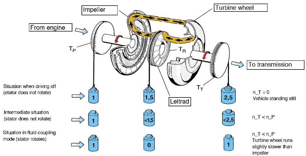
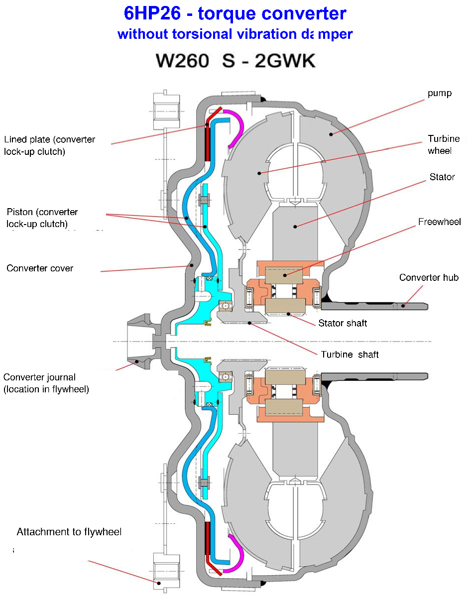
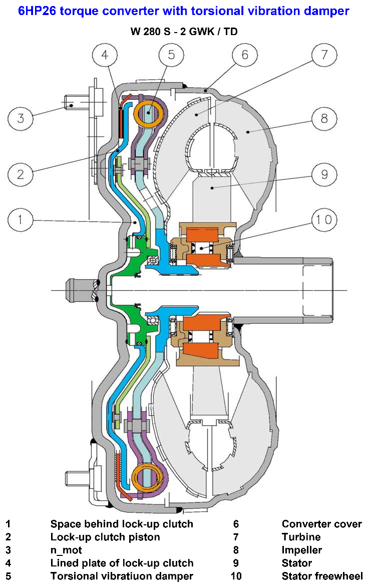
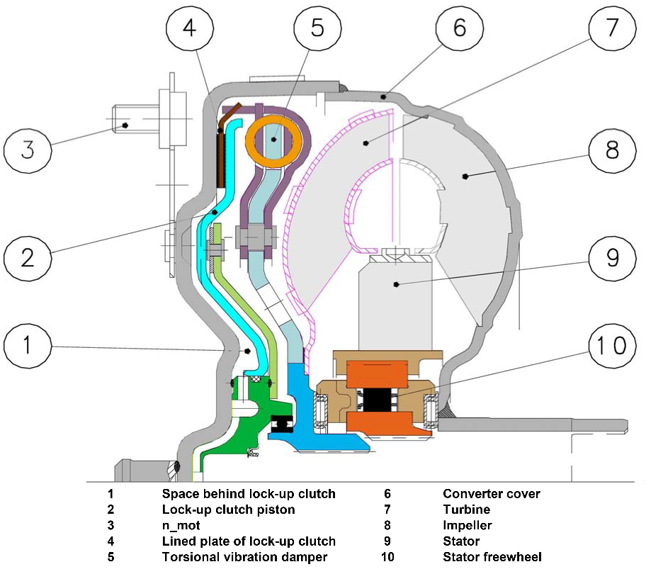
The torque converter consists of the impeller, the turbine wheel, the reaction element (stator) and the oil content needed to transmit the torque.

The impeller, which is driven by the engine, imparts a circular flow to the oil in the converter.
This oil strikes the turbine wheel, which causes the flow to change its direction.

The oil flows out of the turbine wheel close to the hub and strikes the stator, where its direction is changed again to a direction suitable for re-entering the impeller.

The change in direction at the stator generates a torque reaction that increases the torque reaching the turbine.

The ratio between turbine and impeller torque is referred to as torque multiplication or conversion.

The greater the difference in speeds of rotation at the impeller and turbine, the greater the increase in torque; The maximum increase is obtained when the turbine wheel is stationary. As turbine wheel speed increases, the amount of torque multiplication gradually drops.

When the turbine wheel is rotating at about 85 % of the impeller speed, torque conversion reverts to 1, that is to say torque at the turbine wheel is no higher than at the impeller.

The stator, which is prevented from rotating backwards by a freewheel and the shaft in the transmission housing, runs freely in the oil flow and overruns the freewheel. From this point on, the converter acts only as a fluid coupling. During the torque conversion process, the stator ceases to rotate and bears against the housing via the freewheel.

Converter lock-up clutch

The converter lock-up clutch (WK ) is a device that eliminates slip in the torque converter and therefore helps to keep fuel consumption to a minimum.
The WK is engaged and released by the control system. During the actuating phase, a slight difference is selected between the impeller and turbine wheels. This transmits vibration caused by engine rotation to the transmission, after it has been additionally suppressed by a torsional vibration damper.
This procedure ensures optimum shift quality and improves the noise pattern.
Pressure at the WK piston is determined by an electronic pressure control valve (EDS 6 ).
See also the oil flow diagram.
In accordance with the vehicle manufacturer’s wishes, the lock-up clutch can be controlled and engaged in any gear from 1 to 6. The standstill decoupling facility is new. Instead of the engine continuing to drive the converter when the vehicle comes to a standstill (so that the foot has to be kept on the brake), the converter is disconnected from the driveline so that only a slight residual load remains. This further reduces fuel consumption. Decoupling is by actuating clutch A in the transmission, and is dependent on load and output speed.

Hydraulic and mechanical flow in the converter

WK_auf n_Mot > n_Turbine

When released (conversion mode), oil pressures behind the lock-up clutch piston (1) and in the turbine area (2) are equalised. The direction of flow is through the turbine shaft and the area behind the piston into the turbine area.

WK_zu n_Mot = n_Turbine

To engage the lock-up clutch (4) the direction of oil flow in changed (reversed) by a valve
in the hydraulic control unit. At the same
time the space behind the lock-up clutch piston (1) is vented.

Oil pressure extends from the turbine area (3) to the lock-up clutch piston and presses it against cover (5) (outer shell of converter). This locks the turbine wheel (6) by way of the lined disc between the piston and the cover and enables the drive to pass either without slip or with limited slip to the planetary gear train in normal operating conditions.

Oil pump (half-moon pump)

The oil pump is of “half-moon” pattern and delivers app. 16 sq. cm of oil per revolution.
It is located between the torque converter and the transmission housing.


The converter is supported in the pump by a needle roller bearing. The pump is driven directly from the engine via the converter shell and supplies oil to the transmission and the hydraulic control unit.


The pump draws in oil through a filter and delivers it at high pressure to the main pressure valve in the hydraulic control unit. This valve adjusts the pressure and returns excess oil to the oil pan.

Shift elements

The other shift elements in addition to the converter lock-up clutch (WK) are:

    • – three rotating multi-plate clutches A, B and E
    • – two fixed multi-disc brakes C and D

All gear shifts from 1st to 6th or from 6th to 1st are power-on overlapping shifts, that is to say during the shift one of the clutches must continue to transmit the drive at lower main pressure until the other clutch is able to accept the input torque.

The shift elements, clutches or brakes are engaged hydraulically. The oil pressure is built up between the cylinder and the piston, thus pressing the clutch plates together.
When the oil pressure drops, the cup spring pressing against the piston moves it back to its original position.
The purpose of these shift elements is to perform in-load shifts with no interruption to traction.

Multi-plate clutches A, B and E supply power from the engine to the planetary gear train; multi-disc brakes C and D bear against the transmission housing in order to achieve a torque reaction effect.

Example of multi-plate clutch (clutch E)

Clutch E is equalised in terms of dynamic pressure, that is to say its piston is exposed to the oil flow on both sides, in order to prevent pressure build up in the clutch as the speed increases. This equalisation process is achieved by baffle plate (1) and pressure-free oil supply via lubricating passage (2), through which the space between piston and baffle plate is filled with oil.

The advantages of this dynamic pressure equalisation are:

    • – reliable clutch engagement and release
    • in all speed ranges
      – improved shift refinement

Action of shift elements

Shift overlap control

When overlap gear shifts take place, freewheels are not used but are replaced by suitable actuation of the relevant clutches (electronic-hydraulically). This enables both weight and space to be saved.

The electronic-hydraulic shift action is obtained by means of various valves in the hydraulic control unit, actuated by pressure regulators.

They engage or disengage the relevant clutches or brakes at the correct moments.
The electronic control unit is combined with the hydraulic control unit and installed as a single unit in the transmission (Mechatronik).

Parking lock

On the electrical version, the parking lock is engaged by a mechanical spring system in the transmission and secured electrically. All drive positions are also selected electrically. The detent disc in the transmission is omitted, and replaced by a parking disc and lock cylinder with solenoid valve (MV3).
The parking lock is actuated by way of the position switch (hall-effect sensor) on the e-module.


Function:


When the park position is deselected, MV2 resets the parking lock valve in the hydraulic control unit.
The main pressure that is present there reaches the parking lock cylinder and pushes the piston back to release the lock.
MV3 is energised and locks the piston additionally by means of the ball catches.

When the park position is selected, MV3 is de-energised. The mechanical piston lock at the ball catches is released and the piston is able to move.
In this situation, MV2 is also de-energised. The parking lock valve returns to its rest position and vents the parking lock cylinder. The pre-tensioned torsion spring at the parking lock disc pulls the piston in the “park” direction and engages the parking lock.

An additional wire cable at the parking lock disc can be used to release the parking lock manually in certain situations (for instance an electrical failure in the emergency program).

Parking lock operating elements

Controls and shift details

WK_auf n_Mot > n_Turbine